版本:Vivado2020.2(Vitis)
任务:使用 QSPI FALSH 接口实现对 FALSH 的读写操作
目录
一、介绍
(1) Quad-SPI(QSPI)
Zynq SoC 内部集成了专用的 Quad-SPI(QSPI)控制器,用于连接外部串行 NOR Flash 存储器。以下是其主要特点:
接口类型:支持标准SPI(1-bit)、双SPI(2-bit)和四SPI(4-bit)模式
性能:最高可达108MHz时钟频率(在Quad模式下)
容量支持:通常支持16Mb至256Mb的外部Flash芯片
双芯片选择:支持连接两个独立的Flash设备
(2)Flash
Flash 存储器 (闪存) 是一种非易失性电子存储介质,以下是其主要特点:
非易失性:断电后数据不会丢失
可擦写:支持多次擦除和编程(通常10万-100万次)
快速访问:比传统硬盘更快的读写速度
固态结构:无机械部件,抗震性强
按存储结构分为:NOR Flash、NAND Flash 两种:
| NOR Flash | NAND Flash | |
|---|---|---|
| 存储结构 | 随机访问(支持XIP执行) | 块存储(类似硬盘) |
| 读写速度 | 读取快,写入慢 | 写入快,读取较慢 |
| 容量 | 小(1Mb~1Gb) | 大(1Gb~1Tb+) |
| 寿命 | 高(10万~100万次) | 低(1千~10万次) |
| 成本 | 高($/bit) | 低($/bit) |
| 主要用途 | 固件存储、启动设备 | SSD、U盘、大容量存储 |
在通信方式上 Nor Flash 分为两种类型:CFI Flash 和 SPI Flash:
| 特性 | CFI Flash (并行 NOR Flash) | SPI Flash (串行 NOR Flash) |
|---|---|---|
| 接口类型 | 并行总线(地址+数据线,引脚多) | 串行接口(SPI/QSPI,引脚少) |
| 访问速度 | 读写 快 | 读写 慢 |
| 容量 | 较大(16Mb~1Gb+) | 较小(1Mb~256Mb) |
| 引脚占用 | 多(~40+引脚,布线复杂) | 少(4~6引脚,布线简单) |
| 兼容性 | 不同容量硬件不兼容(引脚数量不同) | 不同容量硬件兼容 |
二、硬件设计
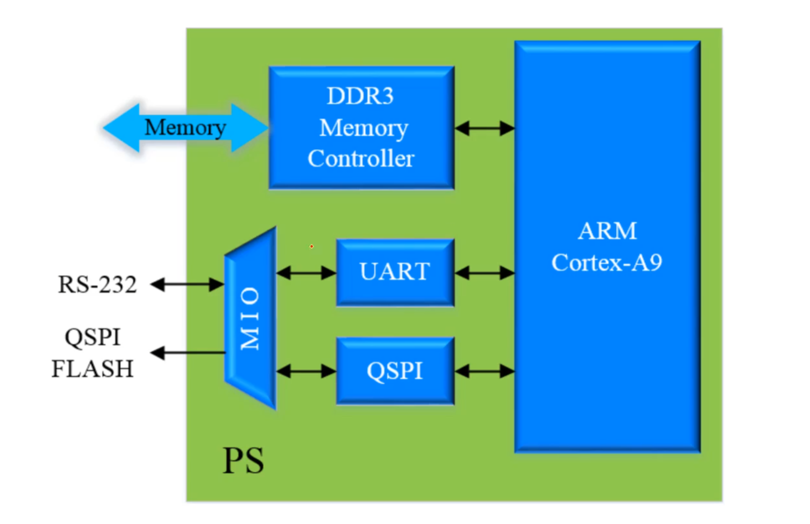
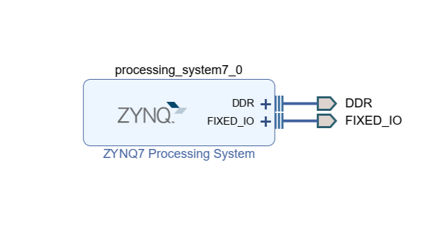
(1)系统框图如图所示,系统搭建用到了QSPI、UART(用于Debug)、DDR(存储器):
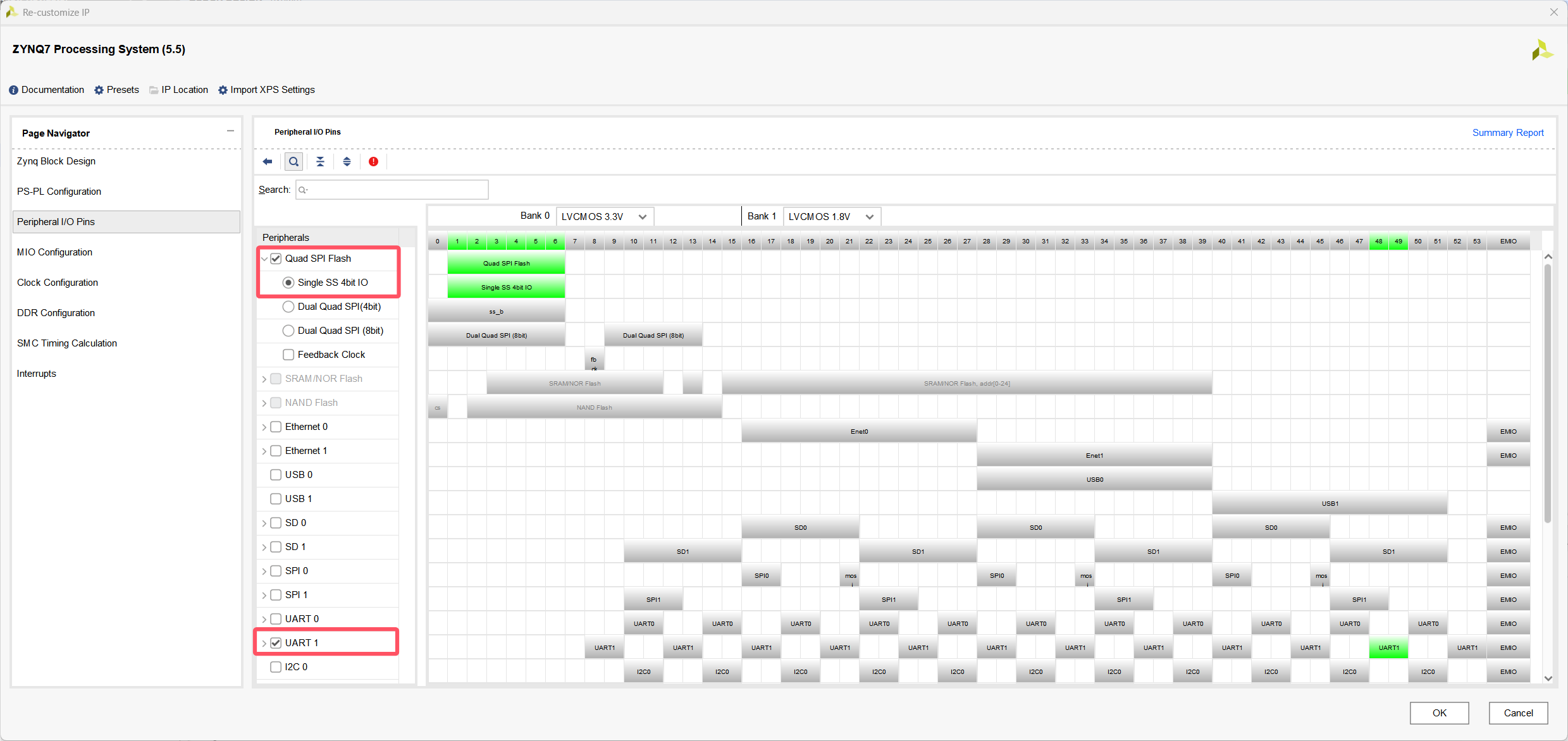
(2)配置QSPI时,选择 “Single”,我所用的 zedboard 开发板只有一个 SPI FALSH ,所以只用一个片选信号即可,如果板卡有两个可以选 “Dual” 有两个片选信号(后面的4/8bit 指数据线数目)。
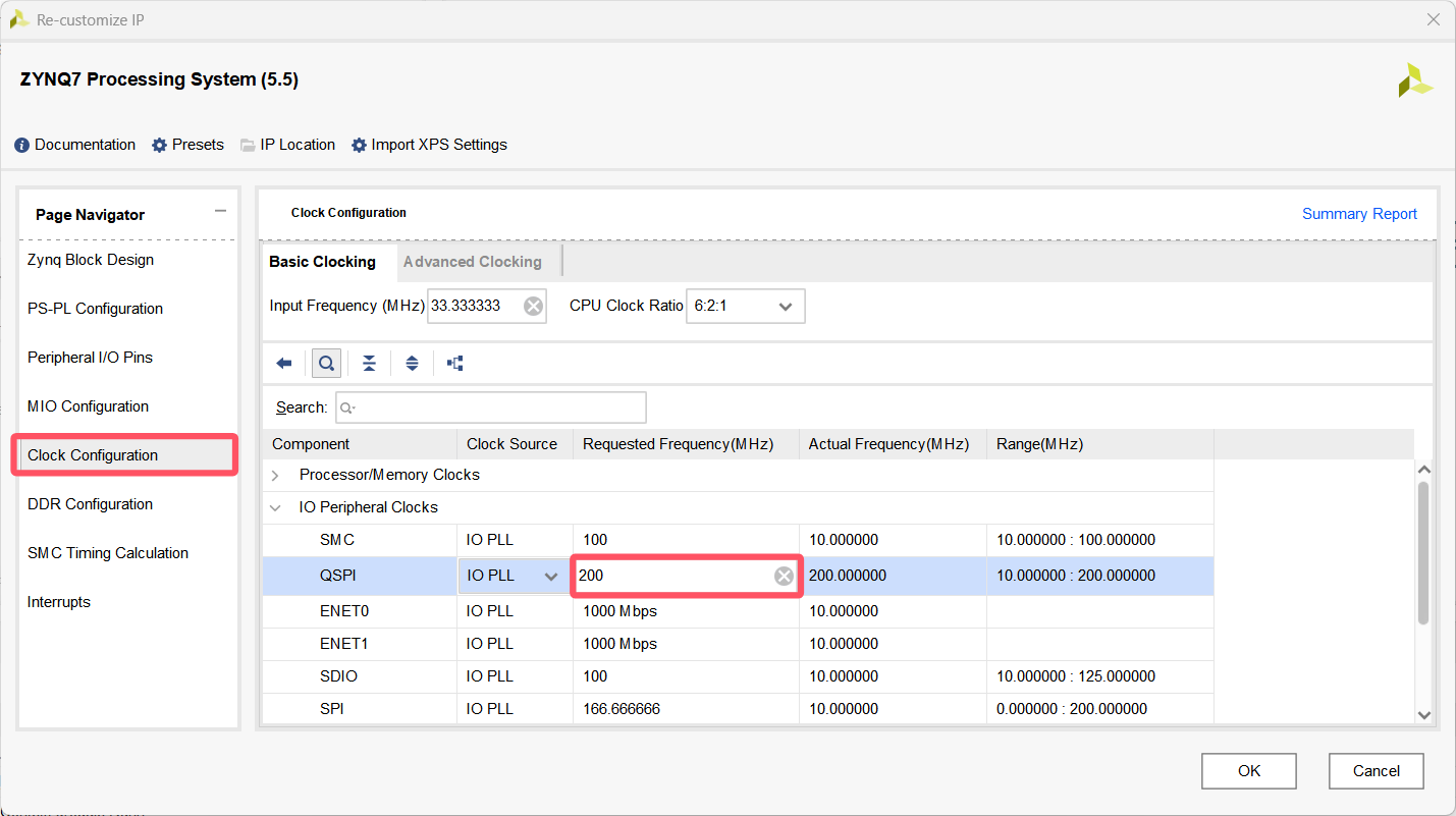
时钟配置栏可以设置QSPI的时钟频率,后续在软件部分可以再次进行分频,这里就直接保持默认的 200 MHz 。
(3)最后整体 bd 设计部分如图所示:设计检查、Generate Output Products、 Create HDL Wrapper、(管脚约束、Gnerate Bitstream、(无PL端设计这两部忽略))、Export Hardware(不用包含比特流文件)、启动Vitis
三、软件设计
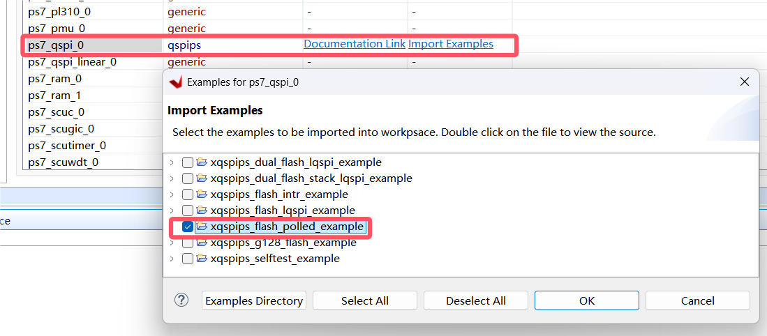
打开官方 QSPI 的示例工程,方便在设计时进行对照参考。这里选轮询的示例工程,这个实例实现对Flash的先写后读,并进行比较,以判断读写操作是否正确
#include "xparameters.h"
#include "xil_printf.h"
#include "xqspips.h"

//==========================自定义宏==========================//
#define QSPI_DEVICE_ID		XPAR_XQSPIPS_0_DEVICE_ID	//宏定义QSPI器件ID

//Flash 存储器命令(根据型号设置)
#define WRITE_STATUS_CMD	0x01 	//写入状态寄存器命令
#define WRITE_CMD			0x02 	//写入数据命令
#define READ_CMD			0x03 	//读取数据命令
#define WRITE_DISABLE_CMD	0x04 	//禁止写入命令
#define READ_STATUS_CMD		0x05 	//读取状态寄存器命令
#define WRITE_ENABLE_CMD	0x06 	//允许写入命令
#define FAST_READ_CMD		0x0B 	//快速读取命令
#define DUAL_READ_CMD		0x3B 	//双通道读取命令
#define QUAD_READ_CMD		0x6B 	//四通道读取命令
#define BULK_ERASE_CMD		0xC7 	//批量擦除命令
#define	SEC_ERASE_CMD		0xD8 	//扇区擦除命令
#define READ_ID				0x9F 	//读取ID命令

//Flash Buffer 中各数据的偏移量
#define COMMAND_OFFSET 		0 		// Flash 指令
#define ADDRESS_1_OFFSET 	1 		// Flash 高字节地址
#define ADDRESS_2_OFFSET 	2 		// Flash 中间字节地址
#define ADDRESS_3_OFFSET 	3 		// Flash 低字节地址
#define DATA_OFFSET 		4 		// 读写数据
#define DUMMY_OFFSET 		4 		// 伪字节

#define DUMMY_SIZE			1 		//伪字节的数量,用于快速、双通道和四通道读取时
#define RD_ID_SIZE			4   	//读取ID命令返回的字节数,包含3个字节的响应
#define BULK_ERASE_SIZE		1		//批量擦除命令的大小
#define SEC_ERASE_SIZE		4 		//扇区擦除命令及其地址的总大小

#define OVERHEAD_SIZE		4		//命令+地址 字节数

//Flash 基本结构定义
#define SECTOR_SIZE			0x10000	//每个扇区的大小,指定为64KB(0x10000字节)
#define NUM_SECTORS			0x100	//总扇区数量,设为256
#define NUM_PAGES			0x10000	//总页数,设为65536
#define PAGE_SIZE			256		//每页的大小,设为256字节

//要写入的闪存页的数量,设为16
#define PAGE_COUNT			16

//本次例程的测试地址和数据
#define TEST_ADDRESS		0x00055000
#define UNIQUE_VALUE		0x05

//可以传输的最大数据量,由要写入的页数和每页字节数乘积得到,最终为4096字节。
#define MAX_DATA	(PAGE_COUNT * PAGE_SIZE)


//===========================实例化===========================//
XQspiPs QspiInstance;   	//QSPI驱动实例

//========================函数变量声明========================//
static void Qspi_Init();	//QSPI初始化函数

//以下函数直接用的示例工程里面的函数(仅最后一个QspiFlashPolledExample函数作了简化修改)
void FlashErase(XQspiPs *QspiPtr, u32 Address, u32 ByteCount);
void FlashWrite(XQspiPs *QspiPtr, u32 Address, u32 ByteCount, u8 Command);
void FlashRead (XQspiPs *QspiPtr, u32 Address, u32 ByteCount, u8 Command);
int  FlashReadID(void);
void FlashQuadEnable(XQspiPs *QspiPtr);
int  QspiFlashPolledExample(XQspiPs *QspiInstancePtr, u16 QspiDeviceId);

int Test = 5;
//读写数据Buffer
u8 ReadBuffer  [MAX_DATA  + DATA_OFFSET + DUMMY_SIZE];
u8 WriteBuffer [PAGE_SIZE + DATA_OFFSET];

//===========================主函数===========================//
int main()
{
	//打印Debug信息
	xil_printf("QSPI Flash Test! \r\n");

	int Status = QspiFlashPolledExample(&QspiInstance, QSPI_DEVICE_ID);
	if (Status != XST_SUCCESS) {
		xil_printf("QSPI Flash Polled Example Test Failed! \r\n");
		return XST_FAILURE;
	}

	xil_printf("Successfully ran QSPI Flash Polled Example Test! \r\n");

	return XST_SUCCESS;
}

//========================QSPI初始化=========================//
void Qspi_Init()
{
    //定义QSPI控制器配置信息(指针)
	XQspiPs_Config *Config;
	//根据QSPI ID,查找配置信息
	Config = XQspiPs_LookupConfig(QSPI_DEVICE_ID);
	//初始化UART控制器驱动
	XQspiPs_CfgInitialize(&QspiInstance, Config, Config->BaseAddress);
	//(可选)QSPI自检
	int Status = XQspiPs_SelfTest(&QspiInstance);
	if (Status != XST_SUCCESS) {
		xil_printf("UART SelfTest Failed! \r\n");
	}
	//设置 QSPI 时钟的分频系数(8分频)
	XQspiPs_SetClkPrescaler(&QspiInstance, XQSPIPS_CLK_PRESCALE_8);
	//设置手动启动和手动片选模式
	XQspiPs_SetOptions(&QspiInstance, XQSPIPS_MANUAL_START_OPTION |
	    	XQSPIPS_FORCE_SSELECT_OPTION |
			XQSPIPS_HOLD_B_DRIVE_OPTION);
}

/*****************************************************************************/
/* 函数功能:初始化读写Buffer、写入数据、读取数据、两数据进行比较验证读写操作是否正确
 *
 * @param	QspiInstancePtr 指向XQspiPs实例的指针
 * @param	QspiDeviceId    QSPI器件ID
 *
 ****************************************************************************/
int QspiFlashPolledExample(XQspiPs *QspiInstancePtr, u16 QspiDeviceId)
{
    u8 *BufferPtr;
    u8  UniqueValue;
    int Count;
    int Page;

    //初始化 QSPI
    Qspi_Init();

    //初始化写数据 BUFFER(从第一个地址依次自增)
    for (UniqueValue = UNIQUE_VALUE, Count = 0; Count < PAGE_SIZE; Count++, UniqueValue++) {
    	WriteBuffer[DATA_OFFSET + Count] = (u8)(UniqueValue + Test);
    }
    //初始化读数据 BUFFER(全部清0)
    memset(ReadBuffer, 0x00, sizeof(ReadBuffer));

    //片选信号置为有效
    XQspiPs_SetSlaveSelect(QspiInstancePtr);
    //读 Flash ID
    FlashReadID();
    //使能 Flash Quad 模式
    FlashQuadEnable(QspiInstancePtr);
    //擦除 Flash
    FlashErase(QspiInstancePtr, TEST_ADDRESS, MAX_DATA);
    //向 Flash 中写入数据
    for (Page = 0; Page < PAGE_COUNT; Page++) {
    	FlashWrite(QspiInstancePtr, (Page * PAGE_SIZE) + TEST_ADDRESS, PAGE_SIZE, WRITE_CMD);
    }
    //使用 QUAD 模式从 Flash 中读出数据
    FlashRead(QspiInstancePtr, TEST_ADDRESS, MAX_DATA, QUAD_READ_CMD);

    //对比写入 Flash 与从 Flash 中读出的数据
    BufferPtr = &ReadBuffer[DATA_OFFSET + DUMMY_SIZE];
    for (UniqueValue = UNIQUE_VALUE, Count = 0; Count < MAX_DATA; Count++, UniqueValue++) {
    	if (BufferPtr[Count] != (u8)(UniqueValue + Test)) {
    		return XST_FAILURE;
    	}
    }

    return XST_SUCCESS;
}

/*****************************************************************************/
/*This function writes to the  serial FLASH connected to the QSPI interface.
* All the data put into the buffer must be in the same page of the device with
* page boundaries being on 256 byte boundaries.
*
* @param	QspiPtr is a pointer to the QSPI driver component to use.
* @param	Address contains the address to write data to in the FLASH.
* @param	ByteCount contains the number of bytes to write.
* @param	Command is the command used to write data to the flash. QSPI
*		device supports only Page Program command to write data to the
*		flash.
*
* @return	None.
* @note		None.
******************************************************************************/
void FlashWrite(XQspiPs *QspiPtr, u32 Address, u32 ByteCount, u8 Command)
{
	u8 WriteEnableCmd = { WRITE_ENABLE_CMD };
	u8 ReadStatusCmd[] = { READ_STATUS_CMD, 0 };  /* must send 2 bytes */
	u8 FlashStatus[2];

	/*
	 * Send the write enable command to the FLASH so that it can be
	 * written to, this needs to be sent as a separate transfer before
	 * the write
	 */
	XQspiPs_PolledTransfer(QspiPtr, &WriteEnableCmd, NULL,
				sizeof(WriteEnableCmd));


	/*
	 * Setup the write command with the specified address and data for the
	 * FLASH
	 */
	WriteBuffer[COMMAND_OFFSET]   = Command;
	WriteBuffer[ADDRESS_1_OFFSET] = (u8)((Address & 0xFF0000) >> 16);
	WriteBuffer[ADDRESS_2_OFFSET] = (u8)((Address & 0xFF00) >> 8);
	WriteBuffer[ADDRESS_3_OFFSET] = (u8)(Address & 0xFF);

	/*
	 * Send the write command, address, and data to the FLASH to be
	 * written, no receive buffer is specified since there is nothing to
	 * receive
	 */
	XQspiPs_PolledTransfer(QspiPtr, WriteBuffer, NULL,
				ByteCount + OVERHEAD_SIZE);

	/*
	 * Wait for the write command to the FLASH to be completed, it takes
	 * some time for the data to be written
	 */
	while (1) {
		/*
		 * Poll the status register of the FLASH to determine when it
		 * completes, by sending a read status command and receiving the
		 * status byte
		 */
		XQspiPs_PolledTransfer(QspiPtr, ReadStatusCmd, FlashStatus,
					sizeof(ReadStatusCmd));

		/*
		 * If the status indicates the write is done, then stop waiting,
		 * if a value of 0xFF in the status byte is read from the
		 * device and this loop never exits, the device slave select is
		 * possibly incorrect such that the device status is not being
		 * read
		 */
		FlashStatus[1] |= FlashStatus[0];
		if ((FlashStatus[1] & 0x01) == 0) {
			break;
		}
	}
}

/*****************************************************************************/
/*This function reads from the  serial FLASH connected to the
* QSPI interface.
*
* @param	QspiPtr is a pointer to the QSPI driver component to use.
* @param	Address contains the address to read data from in the FLASH.
* @param	ByteCount contains the number of bytes to read.
* @param	Command is the command used to read data from the flash. QSPI
*			device supports one of the Read, Fast Read, Dual Read and Fast
*			Read commands to read data from the flash.
*
* @return	None.
*
* @note		None.
******************************************************************************/
void FlashRead(XQspiPs *QspiPtr, u32 Address, u32 ByteCount, u8 Command)
{
	/*
	 * Setup the write command with the specified address and data for the
	 * FLASH
	 */
	WriteBuffer[COMMAND_OFFSET]   = Command;
	WriteBuffer[ADDRESS_1_OFFSET] = (u8)((Address & 0xFF0000) >> 16);
	WriteBuffer[ADDRESS_2_OFFSET] = (u8)((Address & 0xFF00) >> 8);
	WriteBuffer[ADDRESS_3_OFFSET] = (u8)(Address & 0xFF);

	if ((Command == FAST_READ_CMD) || (Command == DUAL_READ_CMD) ||
	    (Command == QUAD_READ_CMD)) {
		ByteCount += DUMMY_SIZE;
	}
	/*
	 * Send the read command to the FLASH to read the specified number
	 * of bytes from the FLASH, send the read command and address and
	 * receive the specified number of bytes of data in the data buffer
	 */
	XQspiPs_PolledTransfer(QspiPtr, WriteBuffer, ReadBuffer,
				ByteCount + OVERHEAD_SIZE);
}

/*****************************************************************************/
/*This function erases the sectors in the  serial FLASH connected to the
* QSPI interface.
*
* @param	QspiPtr is a pointer to the QSPI driver component to use.
* @param	Address contains the address of the first sector which needs to
*			be erased.
* @param	ByteCount contains the total size to be erased.
*
* @return	None.
* @note		None.
******************************************************************************/
void FlashErase(XQspiPs *QspiPtr, u32 Address, u32 ByteCount)
{
	u8 WriteEnableCmd = { WRITE_ENABLE_CMD };
	u8 ReadStatusCmd[] = { READ_STATUS_CMD, 0 };  /* must send 2 bytes */
	u8 FlashStatus[2];
	int Sector;

	/*
	 * If erase size is same as the total size of the flash, use bulk erase
	 * command
	 */
	if (ByteCount == (NUM_SECTORS * SECTOR_SIZE)) {
		/*
		 * Send the write enable command to the FLASH so that it can be
		 * written to, this needs to be sent as a separate transfer
		 * before the erase
		 */
		XQspiPs_PolledTransfer(QspiPtr, &WriteEnableCmd, NULL,
				  sizeof(WriteEnableCmd));

		/* Setup the bulk erase command*/
		WriteBuffer[COMMAND_OFFSET]   = BULK_ERASE_CMD;

		/*
		 * Send the bulk erase command; no receive buffer is specified
		 * since there is nothing to receive
		 */
		XQspiPs_PolledTransfer(QspiPtr, WriteBuffer, NULL,
					BULK_ERASE_SIZE);

		/* Wait for the erase command to the FLASH to be completed*/
		while (1) {
			/*
			 * Poll the status register of the device to determine
			 * when it completes, by sending a read status command
			 * and receiving the status byte
			 */
			XQspiPs_PolledTransfer(QspiPtr, ReadStatusCmd,
						FlashStatus,
						sizeof(ReadStatusCmd));

			/*
			 * If the status indicates the write is done, then stop
			 * waiting; if a value of 0xFF in the status byte is
			 * read from the device and this loop never exits, the
			 * device slave select is possibly incorrect such that
			 * the device status is not being read
			 */
			FlashStatus[1] |= FlashStatus[0];
			if ((FlashStatus[1] & 0x01) == 0) {
				break;
			}
		}

		return;
	}

	/*
	 * If the erase size is less than the total size of the flash, use
	 * sector erase command
	 */
	for (Sector = 0; Sector < ((ByteCount / SECTOR_SIZE) + 1); Sector++) {
		/*
		 * Send the write enable command to the SEEPOM so that it can be
		 * written to, this needs to be sent as a separate transfer
		 * before the write
		 */
		XQspiPs_PolledTransfer(QspiPtr, &WriteEnableCmd, NULL,
					sizeof(WriteEnableCmd));

		/*
		 * Setup the write command with the specified address and data
		 * for the FLASH
		 */
		WriteBuffer[COMMAND_OFFSET]   = SEC_ERASE_CMD;
		WriteBuffer[ADDRESS_1_OFFSET] = (u8)(Address >> 16);
		WriteBuffer[ADDRESS_2_OFFSET] = (u8)(Address >> 8);
		WriteBuffer[ADDRESS_3_OFFSET] = (u8)(Address & 0xFF);

		/*
		 * Send the sector erase command and address; no receive buffer
		 * is specified since there is nothing to receive
		 */
		XQspiPs_PolledTransfer(QspiPtr, WriteBuffer, NULL,
					SEC_ERASE_SIZE);

		/*
		 * Wait for the sector erse command to the
		 * FLASH to be completed
		 */
		while (1) {
			/*
			 * Poll the status register of the device to determine
			 * when it completes, by sending a read status command
			 * and receiving the status byte
			 */
			XQspiPs_PolledTransfer(QspiPtr, ReadStatusCmd,
						FlashStatus,
						sizeof(ReadStatusCmd));

			/*
			 * If the status indicates the write is done, then stop
			 * waiting, if a value of 0xFF in the status byte is
			 * read from the device and this loop never exits, the
			 * device slave select is possibly incorrect such that
			 * the device status is not being read
			 */
			FlashStatus[1] |= FlashStatus[0];
			if ((FlashStatus[1] & 0x01) == 0) {
				break;
			}
		}

		Address += SECTOR_SIZE;
	}
}

/*****************************************************************************/
/* This function reads serial FLASH ID connected to the SPI interface.
*
* @param	None.
*
* @return	XST_SUCCESS if read id, otherwise XST_FAILURE.
* @note		None.
******************************************************************************/
int FlashReadID(void)
{
	int Status;

	/* Read ID in Auto mode.*/
	WriteBuffer[COMMAND_OFFSET]   = READ_ID;
	WriteBuffer[ADDRESS_1_OFFSET] = 0x23;		/* 3 dummy bytes */
	WriteBuffer[ADDRESS_2_OFFSET] = 0x08;
	WriteBuffer[ADDRESS_3_OFFSET] = 0x09;

	Status = XQspiPs_PolledTransfer(&QspiInstance, WriteBuffer, ReadBuffer,
				RD_ID_SIZE);
	if (Status != XST_SUCCESS) {
		return XST_FAILURE;
	}

	xil_printf("FlashID=0x%x 0x%x 0x%x\n\r", ReadBuffer[1], ReadBuffer[2],
		   ReadBuffer[3]);

	return XST_SUCCESS;
}

/*****************************************************************************/
/* This function enables quad mode in the serial flash connected to the
 * SPI interface.
 *
 * @param	QspiPtr is a pointer to the QSPI driver component to use.
 *
 * @return	None.
 * @note	None.
 ******************************************************************************/
void FlashQuadEnable(XQspiPs *QspiPtr)
{
	u8 WriteEnableCmd = {WRITE_ENABLE_CMD};
	u8 ReadStatusCmd[] = {READ_STATUS_CMD, 0};
	u8 QuadEnableCmd[] = {WRITE_STATUS_CMD, 0};
	u8 FlashStatus[2];


	if (ReadBuffer[1] == 0x9D) {

		XQspiPs_PolledTransfer(QspiPtr, ReadStatusCmd,
					FlashStatus,
					sizeof(ReadStatusCmd));

		QuadEnableCmd[1] = FlashStatus[1] | 1 << 6;

		XQspiPs_PolledTransfer(QspiPtr, &WriteEnableCmd, NULL,
				  sizeof(WriteEnableCmd));

		XQspiPs_PolledTransfer(QspiPtr, QuadEnableCmd, NULL,
					sizeof(QuadEnableCmd));
		while (1) {
			/*
			 * Poll the status register of the FLASH to determine when
			 * Quad Mode is enabled and the device is ready, by sending
			 * a read status command and receiving the status byte
			 */
			XQspiPs_PolledTransfer(QspiPtr, ReadStatusCmd, FlashStatus,
					sizeof(ReadStatusCmd));
			/*
			 * If 6th bit is set & 0th bit is reset, then Quad is Enabled
			 * and device is ready.
			 */
			if ((FlashStatus[0] == 0x40) && (FlashStatus[1] == 0x40)) {
				break;
			}
		}
	}
}
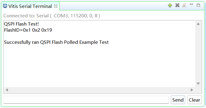
四、效果