本原创文章由深圳市小眼睛科技有限公司创作,版权归本公司所有,如需转载,需授权并注明出处(www.meyesemi.com)
1. 实验简介
实验目的:
实现 3X3 图像矩阵对应 9 个像素点图像数据的读取。
实验环境:
Window11
PDS2022.SP6.4
Modelsim10.6c
MatlabR2023b(可以用别的版本)
硬件环境:
MES2L676-100HP
2. 实验原理
在数字图像处理中,部分算法需根据每个像素点及其周围一定范围内的像素点数据进行计算,图像矩阵的 生成至关重要。本系列图像处理实验主要采用 3X3 图像矩阵实现对应图像处理算法。
例如一幅完整的 5X5 图像如下图所示,每个方格表示一个像素点,方格内的数字表示对应像素点的像素数据。
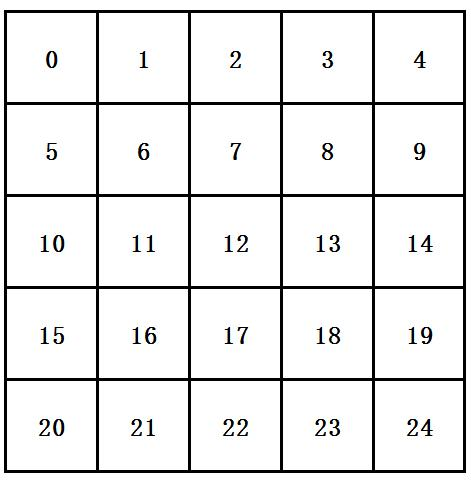
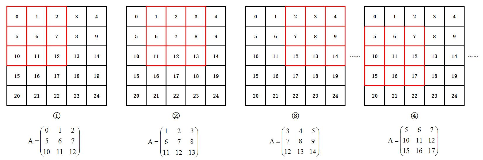
3X3 图像矩阵的行对应图像一行中三个连续的像素点,3X3 图像矩阵的列对应图像一列中三个连续的像素点,矩阵的元素对应图像的像素数据。在 5X5 的图像中,按图像的扫描方式从左到右,从上到下地获取对应 3X3 图像矩阵的数据
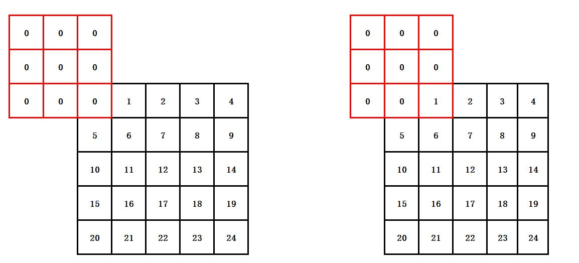
在图像处理算法中,若通过每个 3X3 图像矩阵计算中心像素点的像素数据,为保证图像分辨率不变,在图 像左侧两列和上方两行的位置对像素数据补“0”操作,如下图所示:
基于以上分析,在图像数据按行输入的情况下,为获取 3X3 图像矩阵需同时输出三行图像中的数据,因此 采用 FPGA 的缓存资源(fifo/ram)将接收的每一行数据进行缓存,并且在输出 3X3 图像矩阵数据时输出当前 第 n 行对应位置的数据、第 n-1 行对应位置的数据以及第 n-2 行对应位置的数据。另外,为缓存第 n-1 行图像 数据和第 n-2 行图像数据,需调用 2 个 fifo 缓存模块,并且实现当前数据缓存到第 n-1 行图像数据缓存 fifo, 从第 n-1 行图像数据缓存 fifo 读出后再缓存到第 n-2 行图像数据缓存 fifo,确保 3X3 矩阵输出时读取两个 fifo可同时获得第 n-1 行和第 n-2 行的数据。FPGA 实现 3X3 图像矩阵具体方案框图如下:
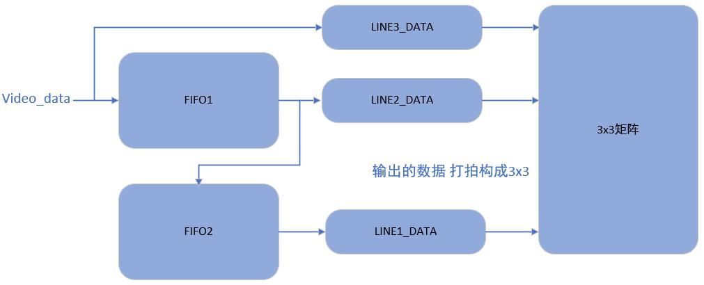
按行输入的图像数据 video_data 在数据有效期间缓存到 fifo1,同时 fifo1 读出一行数据进入 fifo2 缓存, 且 fifo2 同时读出一行数据,若 fifo1 或 fifo2 为空则输出 0。数据输出过程如下图所示:
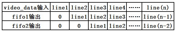
此外,实现同时输出连续三行图像数据后,需注意所输出的三个数据对应在一行中的位置保持一致。
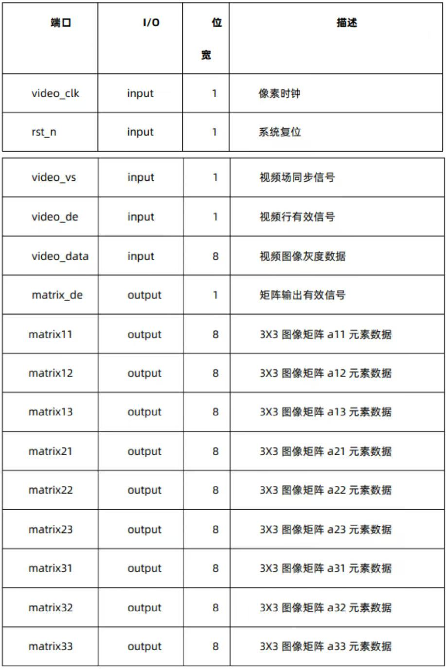
3. 接口列表
以下为 matrix_3x3.v 模块的接口列表。
4. 工程说明
4.1. 代码模块说明
3X3 图像矩阵生成模块代码如下所示:
// 3x3 矩阵生成
module matrix_3x3
#(
    parameter IMG_WIDTH = 11'd1920,
    parameter IMG_HEIGHT = 11'd1080
)
(
    input wire video_clk,
    input wire rst_n,
    input wire video_vs,
    input wire video_de,
    input wire [7:0] video_data,  // 3x3 矩阵输出

    output wire matrix_de,
    output reg [7:0] matrix11,
    output reg [7:0] matrix12,
    output reg [7:0] matrix13,
    output reg [7:0] matrix21,
    output reg [7:0] matrix22,
    output reg [7:0] matrix23,
    output reg [7:0] matrix31,
    output reg [7:0] matrix32,
    output reg [7:0] matrix33
);

    // wire define
    wire [7:0] line3_data;  // 第三行数据
    wire [7:0] line2_data;  // 第二行数据
    wire [7:0] line1_data;  // 第一行数据
    wire wr_fifo_en;        // 写 FIFO 使能
    wire rd_fifo_en;        // 读 FIFO 使能

    // reg define
    reg [10:0] x_cnt;
    reg [10:0] y_cnt;

    // 列计数
    always @(posedge video_clk or negedge rst_n) begin
        if (!rst_n)
            x_cnt <= 11'd0;
        else if (x_cnt == IMG_WIDTH - 1)  // 计数一行
            x_cnt <= 11'd0;
        else if (video_de)  // 数据有效
            x_cnt <= x_cnt + 1'b1;
        else
            x_cnt <= x_cnt;
    end

    // 行计数
    always @(posedge video_clk or negedge rst_n) begin
        if (!rst_n)
            y_cnt <= 11'd0;
        else if (y_cnt == IMG_HEIGHT - 1 && x_cnt == IMG_WIDTH - 1)  // 计数一帧
            y_cnt <= 11'd0;
        else if (x_cnt == IMG_WIDTH - 1)  // 数据有效
            y_cnt <= y_cnt + 1'b1;
        else
            y_cnt <= y_cnt;
    end
以上代码根据模块接口列表,定义模块端口及对输入数据进行行/列计数
// 3x3 矩阵 第一行和最后一行无法构成
assign wr_fifo_en = video_de && (y_cnt < IMG_HEIGHT-1);
assign rd_fifo_en = video_de && (y_cnt > 0);

reg wr_fifo_en_1d;
reg [7:0] video_data_1d;

always @(posedge video_clk or negedge rst_n) begin
    if (!rst_n) begin
        wr_fifo_en_1d <= 1'd0;
        video_data_1d <= 8'd0;
    end
    else begin
        wr_fifo_en_1d <= wr_fifo_en;
        video_data_1d <= video_data;
    end
end

// 通过两个 FIFO 与当前的输入一起构成 3x3 矩阵
assign line3_data = video_data_1d;

// fifo1
fifo_line_buffer u1_fifo_line_buffer (
    .wr_clk      (video_clk),    // input
    .wr_rst      (~rst_n),       // input
    .wr_en       (wr_fifo_en),   // input
    .wr_data     (video_data),   // input [7:0]
    .wr_full     (),             // output
    .almost_full (),             // output
    .rd_clk      (video_clk),    // input
    .rd_rst      (~rst_n),       // input
    .rd_en       (rd_fifo_en),   // input
    .rd_data     (line2_data),   // output [7:0]
    .rd_empty    (u1_empty),     // output
    .almost_empty()              // output
);

// fifo2
fifo_line_buffer u2_fifo_line_buffer (
    .wr_clk      (video_clk),    // input
    .wr_rst      (~rst_n),       // input
    .wr_en       (wr_fifo_en_1d),// input
    .wr_data     (line2_data),   // input [7:0]
    .wr_full     (),             // output
    .almost_full (),             // output
    .rd_clk      (video_clk),    // input
    .rd_rst      (~rst_n),       // input
    .rd_en       (rd_fifo_en),   // input
    .rd_data     (line1_data),   // output [7:0]
    .rd_empty    (),             // output
    .almost_empty()              // output
);
以上代码实现两级 fifo 对图像数据按行缓存。为确保三行数据输出保持同步,需注意 fifo 读出数据相较于 fifo 读使能信号延时 1 个时钟周期,因此 line3_data 数据需将当前输入数据延迟 1 个时钟周期,与 fifo 输出的 line2_data 和 line1_data 保持同步,并且 fifo1 输出数据写入 fifo2 时也需要将 fifo1 的读使能信号延时 1 个 时钟周期再作为 fifo2 的写使能信号。
// 数据延迟 de 延迟
reg video_de_d0;
reg video_de_d1;

always @(posedge video_clk or negedge rst_n) begin
    if (!rst_n) begin
        video_de_d0 <= 1'd0;
        video_de_d1 <= 1'd0;
    end
    else begin
        video_de_d0 <= video_de;
        video_de_d1 <= video_de_d0;
    end
end

// 矩阵数据生成
always @(posedge video_clk or negedge rst_n) begin
    if (!rst_n) begin
        {matrix11, matrix12, matrix13} <= 24'd0;
        {matrix21, matrix22, matrix23} <= 24'd0;
        {matrix31, matrix32, matrix33} <= 24'd0;
    end
    else if (video_de_d0) begin
        {matrix11, matrix12, matrix13} <= {matrix12, matrix13, line1_data};
        {matrix21, matrix22, matrix23} <= {matrix22, matrix23, line2_data};
        {matrix31, matrix32, matrix33} <= {matrix32, matrix33, line3_data};
    end
    else begin
        {matrix11, matrix12, matrix13} <= 24'd0;
        {matrix21, matrix22, matrix23} <= 24'd0;
        {matrix31, matrix32, matrix33} <= 24'd0;
    end
end

// 矩阵数据有效输出
assign matrix_de = video_de_d1;
assign matrix_vs = video_vs;

endmodule
以上代码实现 3X3 图像矩阵的生成。三行数据同时输出,每一行的数据按“打拍”方式移位实现矩阵的位 置的移动,需注意输出数据在生成矩阵时产生 1 个时钟周期的延时,因此最终数据的矩阵有效信号 matrix_de 也需延时 1 个时钟周期。
4.2. 代码仿真
在 modelsim 平台,matrix_3x3 模块的仿真激励模块 matrix_tb.v 生成 5x5 的图像数据源,仿真分析结果如下:
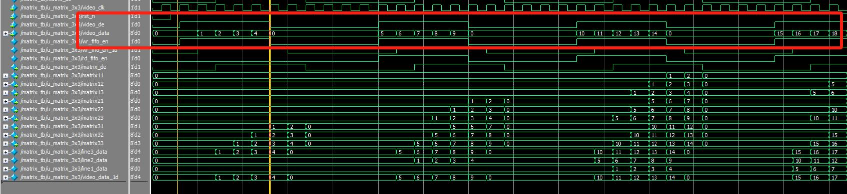
5x5 的图像数据源符合以下图像示意图:
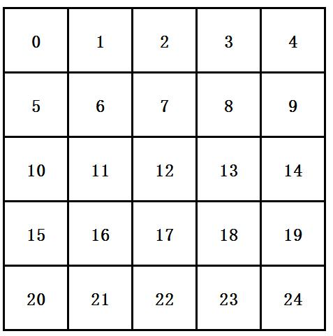
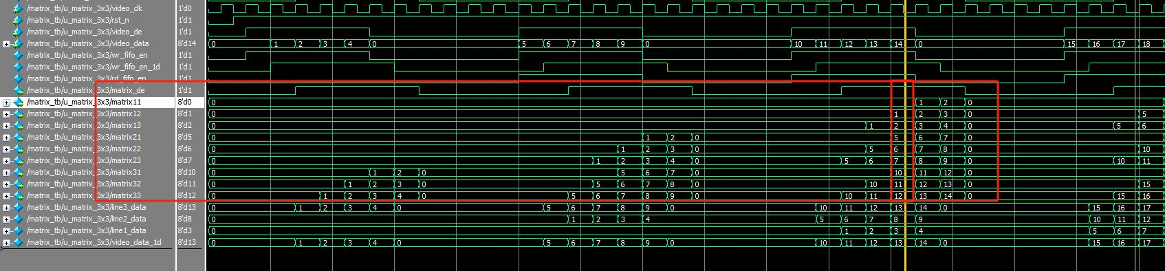
3X3 图像矩阵的生成符合预期。